


Doebritz Powder Handling Expertise
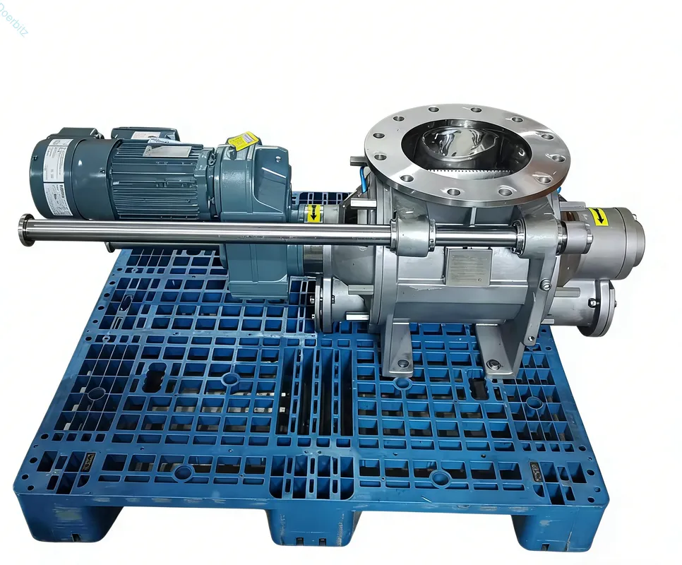
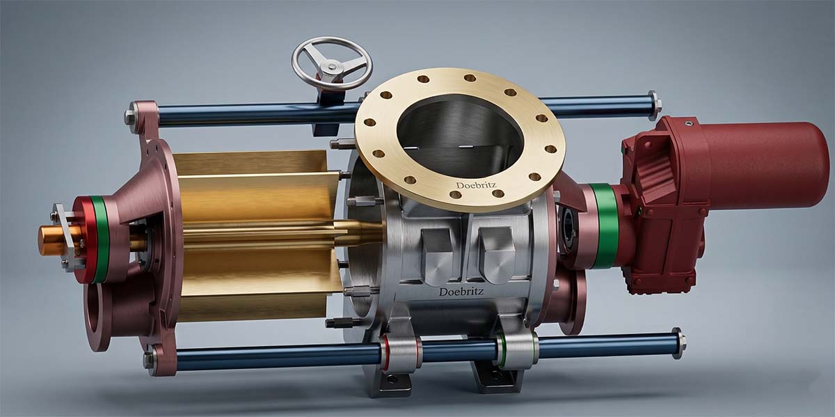
Doebritz is a professional manufacturer of powder handling equipment. Over many decades, our teams have designed, tested, and improved bulk material transfer solutions for industrial facilities around the world. Every day, our engineers work directly with plant managers, maintenance staff, and system designers who deal with difficult material feed challenges in the chemical, food processing, and plastics industries. This hands-on manufacturing and troubleshooting experience has given us a thorough understanding of how bulk solids behave. When clients ask us how does a rotary valve work, we explain that it is far more than a simple spinning paddle. It is a carefully engineered precision instrument built to meter material and seal against pressure differences at the same time. In this detailed guide, we share our direct factory knowledge and field experience to help you understand the basic mechanics of these essential components. Our goal is to make sure your production lines run with maximum reliability, as little downtime as possible, and the highest safety standards available.
Flow Control in Pneumatic Systems
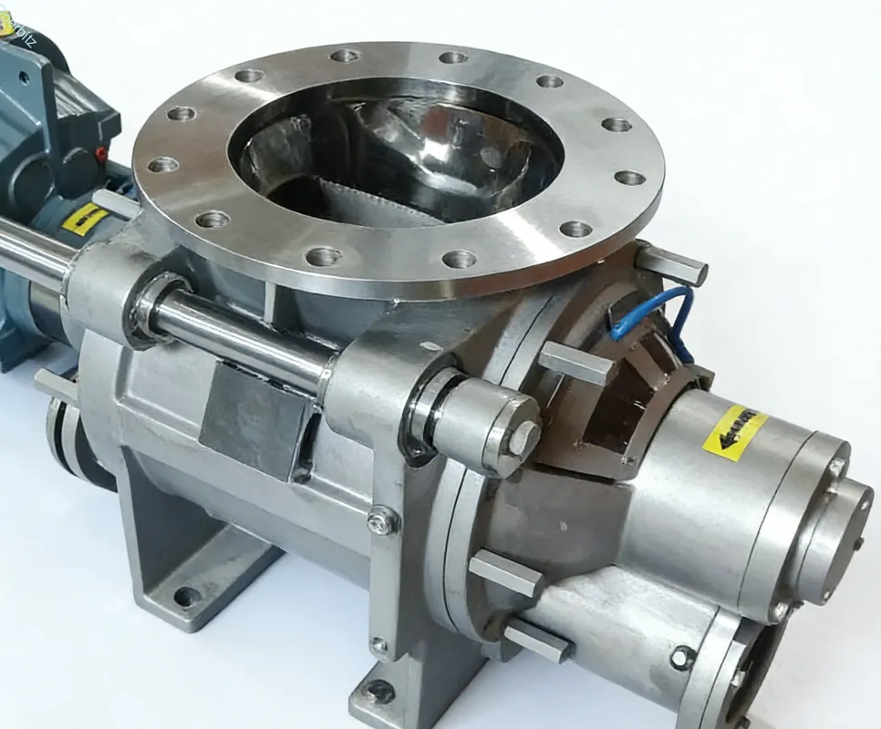
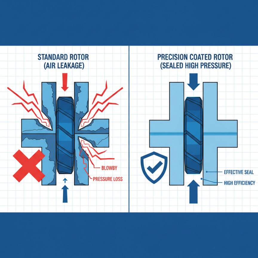
To truly understand how bulk material transfer works, we need to answer the most important question: how does a rotary valve control flow in pneumatic conveying systems. At its core, the process depends on the careful coordination of rotor speed, pocket volume, and pressure differential management. Unlike gravity-fed setups, conveying lines operate under significant air pressure. The valve must act as an airlock, keeping a tight seal between the high-pressure conveying line and the low-pressure storage hopper sitting above it. If this seal breaks down, conveying air rushes upward into the hopper — a problem known as blowback — which stops material from entering the rotor pockets and completely disrupts the flow rate.
Our engineering data shows that maintaining strong volumetric efficiency, typically between seventy and eighty percent in high-pressure environments, requires strict attention to three core principles:
- Volumetric Displacement: The physical size of the rotor pockets determines the maximum volume of material that can be moved per revolution. We engineer the internal geometry so that each pocket fills consistently without bridging or packing, which allows for a predictable and steady discharge rate into the conveying pipeline.
- RPM Calibration: Rotor speed is not chosen randomly. We set the RPM specifically to match the required system feed rate. Running at speeds that are too high reduces the time available for material to drop into the pockets, which — somewhat surprisingly — actually lowers the real feed rate, raises the risk of product damage, and speeds up mechanical wear.
- Pressure Sealing: Keeping air leakage to a minimum is arguably the most important part of flow control. The tight gaps between the rotor tips and the inside of the housing stop conveying air from escaping upward. By effectively managing this pressure difference, the valve ensures that gravity and the rotational sweep of the blades are the only forces moving material downward.
When these three elements are perfectly balanced, the system achieves a smooth, continuous feed that prevents line choking, reduces energy use, and maximizes overall conveying efficiency. Our factory testing consistently confirms that precision machining of the housing and rotor is the absolute foundation of reliable flow control in any pressurized environment.
Material Traits Affecting Valve Sizing
The physical properties of a bulk material fundamentally change the flow control dynamics. When plant engineers ask how does a rotary valve work with highly variable substances, we stress that a one-size-fits-all approach will almost certainly lead to system failure. The bulk density, moisture content, particle size, and flowability of a product all determine the specific sizing and rotor configuration needed to maintain a consistent feed. Fine, easily aerated powders behave in completely different ways compared to coarse, abrasive granules under pressure.
If a valve is incorrectly sized for a cohesive material, the product will stick to the internal pockets, shrinking the effective volume and starving the pneumatic line. On the other hand, highly abrasive materials require specialized clearances and hardened surfaces to prevent rapid breakdown of the sealing envelope. To help system designers choose the right equipment, we have put together a reference guide based on our extensive material testing laboratory results.
| Material Characteristic | Common Examples | Recommended Rotor and Clearance Adjustment |
| Abrasive | Cement, Fly Ash, Sand | Closed-end rotor, hardened housing, tight clearances, wear-resistant coatings |
| Cohesive and Sticky | Titanium Dioxide, Moist Flour | Open-end rotor, polished or Teflon-coated pockets, shallow pocket geometry |
| Heat-Sensitive | Sugar, Resin Pellets | Relieved rotor tips, slightly increased clearances to prevent friction melting |
| Easily Aerated | Hydrated Lime, Fine Talc | Maximum sealing envelope, exceptionally tight tolerances, venting ports |
By matching the mechanical design to the specific traits of the material, we ensure continuous flow, prevent unexpected blockages, and protect the integrity of the entire conveying process. Proper sizing is the first and most important defense against operational instability.
Resolving Wear and Leakage Problems
Even the most precisely engineered systems can break down over time when exposed to harsh operating conditions. Understanding the rotary valve working principle wear and leakage problems is essential for long-term maintenance and system troubleshooting. When the tight clearances between the rotor and the housing grow wider due to continuous abrasion, high-pressure air bypasses the rotor tips. This blowby not only stops material from flowing downward but also speeds up internal wear, as abrasive particles are blasted through the widening gaps at high velocities.
To illustrate this damaging cycle, we share a detailed case study involving a large-scale cement manufacturing plant in Vietnam. The facility was experiencing major disruptions in their fly ash conveying lines, which led to serious production bottlenecks.
“Our pneumatic conveying system is completely erratic. We are seeing massive air blowback into the feed hopper, the feed rate has dropped by forty percent, and our standard carbon steel valves are wearing out every three months. We cannot maintain production under these conditions.”
After receiving this urgent request, our technical support team began a thorough diagnostic process. First, we reviewed the operating parameters and noted that the system ran at elevated temperatures of one hundred and fifty degrees Celsius with a highly abrasive material and a significant pressure differential of fifteen PSI. We measured the existing rotor-to-housing clearances and found they had grown to over three millimeters — well beyond the acceptable tolerance for an effective airlock.
To fix this, we engineered a custom solution designed specifically for their environment. We replaced the standard unit with a heavy-duty Doebritz valve featuring a specialized tungsten-carbide coating on the internal housing. This coating provides strong resistance to the abrasive sliding action of fly ash.
Next, we installed a closed-end rotor fitted with adjustable, hardened steel tips. This specific design allowed the maintenance team to manually reset the clearances back to the factory specification of zero point one millimeters as minor wear occurred over time, rather than replacing the entire rotor assembly.
Finally, we added a specialized venting system to redirect any remaining displaced air away from the incoming material stream. After the installation was complete, the blowback was fully eliminated. The plant restored their feed rate to one hundred percent capacity, and the new valve has run continuously for over eighteen months without needing a major overhaul. This real-world result demonstrates our commitment to building durable solutions for the most demanding industrial environments.
Enhance System Performance Today
Achieving optimal material transfer in your facility requires more than simply installing standard equipment. It demands a solid understanding of pneumatic dynamics, material characteristics, and precision engineering. As we have explained throughout this guide, maintaining strict pressure seals, calibrating volumetric displacement, and proactively dealing with abrasive wear are the absolute cornerstones of a highly efficient production line. Doebritz remains committed to providing the technical expertise and strong manufacturing quality needed to overcome your most serious bulk handling challenges.
If you are currently experiencing erratic feed rates, severe air blowback, or premature equipment failure, do not let inefficient components bottleneck your production. We invite you to contact our engineering support team with your specific system details, material properties, and operating pressures by emailing us directly at sales@rotaryvalveco.com for a customized flow control consultation. Let us help you design a solution that guarantees long-term reliability and peak operational efficiency.