


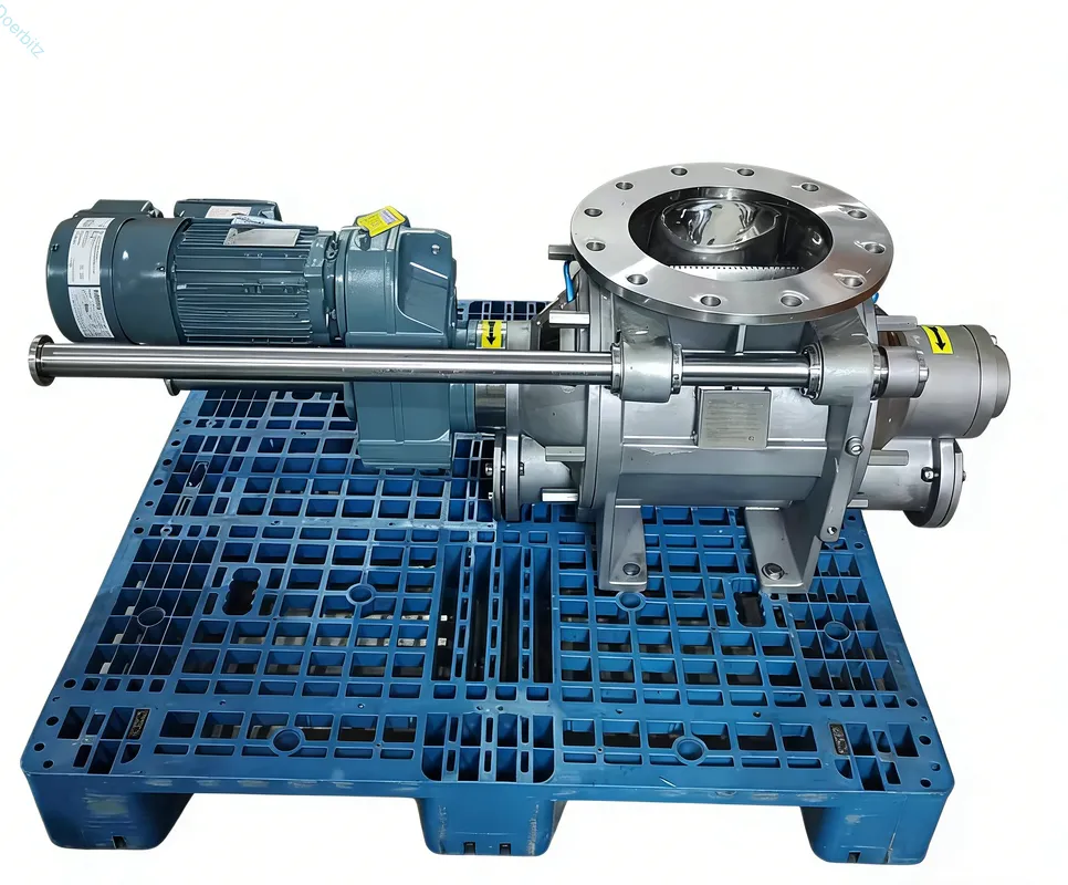
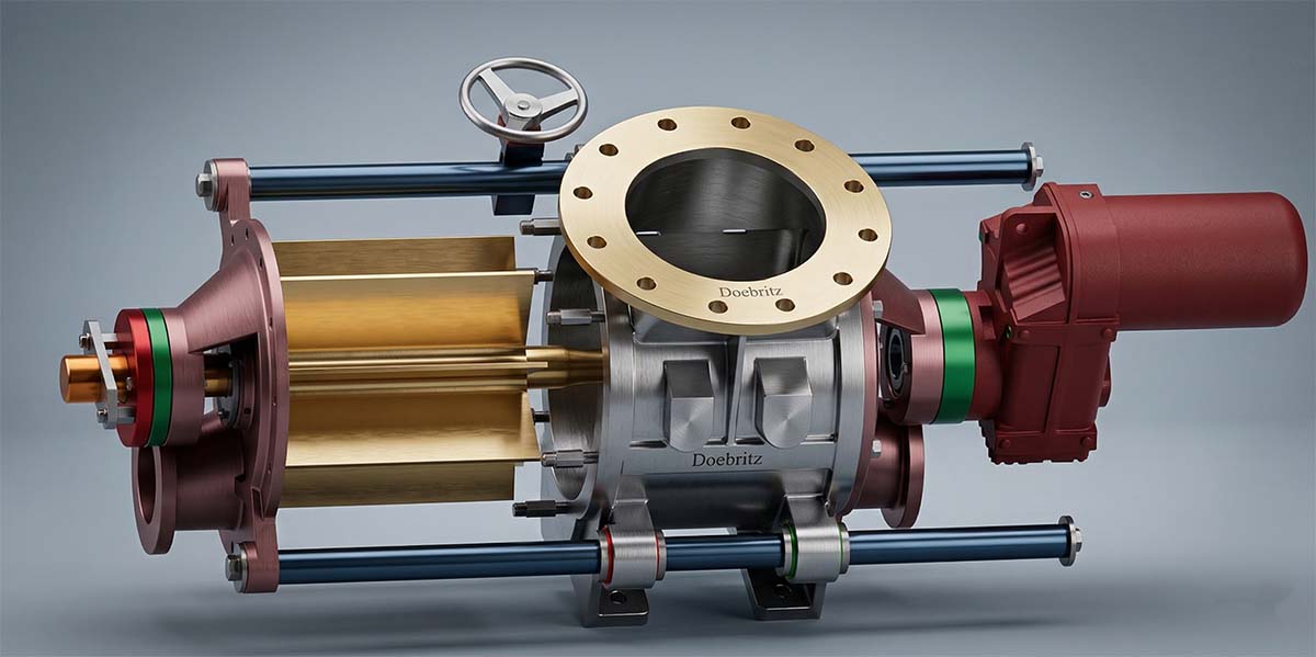
Plant engineers frequently struggle with retrofitting equipment into legacy buildings. They face severe head-space constraints, multiple 90-degree turns, and chronic material blockages. As Doebritz, a professional manufacturer of powder handling rotary valves, we have spent decades engineering solutions for these exact spatial nightmares. We see facilities lose massive throughput due to poorly routed piping in tight corners.
A custom pneumatic conveyor design for irregular facility floor plans is an engineered routing and pressure-balancing strategy. It utilizes specialized bends, precise air-to-cloth ratios, and custom rotary valves to navigate structural obstacles without sacrificing material velocity.
This guide breaks down the exact pressure calculations, bend radius parameters, and real-world retrofit strategies needed to optimize complex material handling. By applying our engineering data, you will learn how to bypass structural limitations and achieve seamless powder transfer in any non-standard building footprint.
Why Do Irregular Layouts Cause Failures?
Irregular layouts force multiple pipe bends and tight sweeps, directly increasing friction, material degradation, and frictional pressure drops.
Every directional change in a conveying line impacts the material velocity. When piping must navigate around existing support columns or low ceilings, standard engineering assumptions fail. Blind spots in L-shaped buildings frequently cause material saltation. This happens when the conveying air velocity drops below the minimum threshold required to keep particles suspended. The material falls out of the air stream, accumulating at the bottom of the pipe until a total system blockage occurs.
We measure a minimum conveying velocity drop of 15 m/s across poorly designed junctions. These drops trigger severe pressure spikes ranging from 1.2 to 1.5 bar. This immediately overloads the blower system. Facilities suffer a 20 percent efficiency loss caused entirely by standard short-radius elbows installed in tight spaces. We must calculate these exact resistance points to prevent system blockages.
| Bend Configuration | Pressure Drop Penalty (psi) | Velocity Loss (%) | Wear Rate Factor |
| Standard 2D Radius | 2.5 | 18 | High |
| Sweeping 5D Radius | 1.1 | 6 | Moderate |
| Engineered Long Sweep | 0.4 | 2 | Minimal |
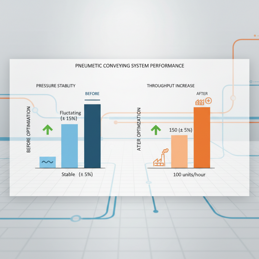
How Does System Retrofitting Improve Performance?
A pneumatic conveyor system retrofit for non-standard plant configurations leverages existing infrastructure while upgrading critical routing junctions, drastically reducing installation downtime.
Complete system replacements are rarely financially viable for existing irregular plants. Structural demolition requirements make new installations prohibitively expensive. Targeted retrofitting corrects legacy layout flaws without requiring a highly expensive facility rebuild. We identify specific bottlenecks and upgrade only the necessary components.
Upgrading from 2-inch to 4-inch piping in specific non-standard corridors drastically increases volumetric capacity. This localized expansion decreases the air velocity while maintaining the required pressure differential. When clients search for the best custom pneumatic conveyors for unique plant layouts, they actually need this surgical retrofit approach. We recently executed a modular retrofit plan that reduced facility downtime from a projected 21 days to just 48 hours.
- 40 percent capital expenditure savings compared to total system replacement
- 48-hour installation downtime versus 21-day facility shutdown
- 30 percent footprint reduction using modular diverter valves
- 50 tons/hr throughput recovery by eliminating chronic choke points
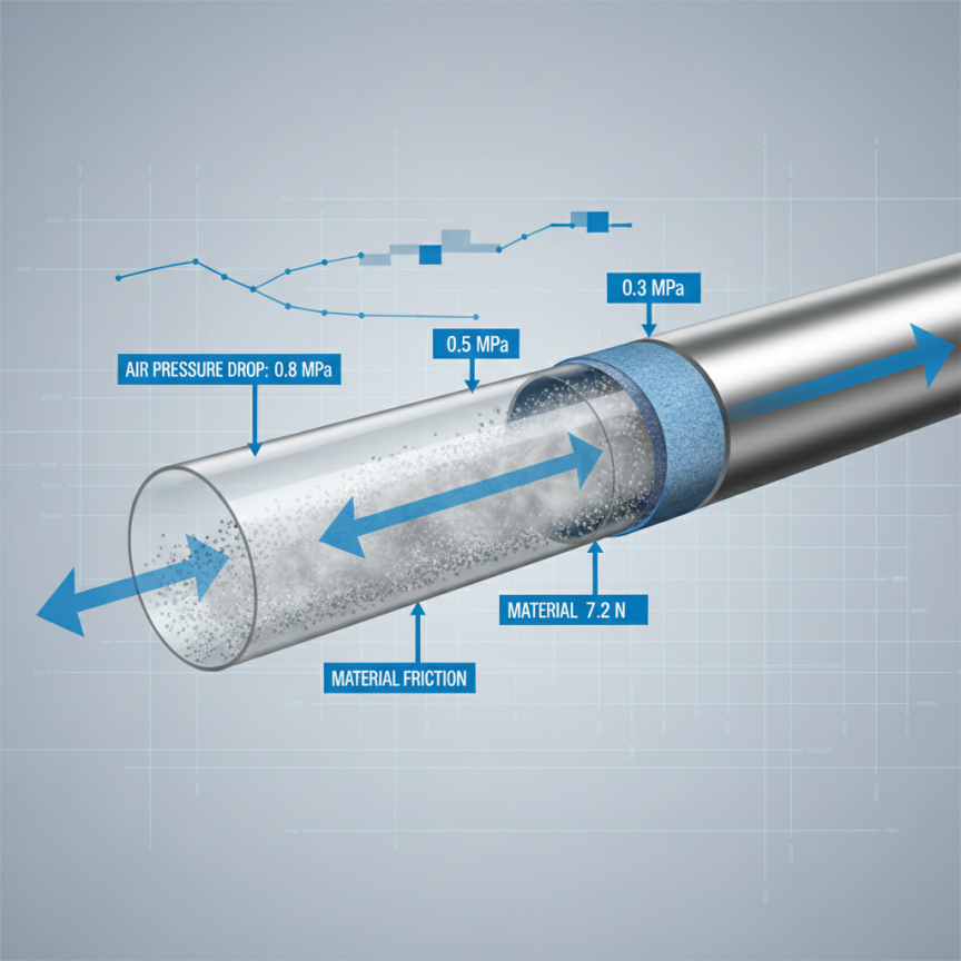
What Drives Pressure Drop Spikes?
Pressure drop spikes occur when conveying air encounters sudden directional shifts in non-standard configurations, forcing the blower to work against exponentially higher resistance.
We mitigate this by calculating the equivalent pipe length for every irregular turn. A single tight 90-degree bend equals 10 meters of straight pipe resistance. When a layout forces four such bends within a short distance, the system suddenly behaves as if it were 40 meters longer. This mathematical reality dictates blower sizing and rotary valve selection.
How Did We Fix Complex Layouts?
By engineering a multi-stage routing strategy with customized rotary airlocks, we bypassed structural obstacles while maintaining constant conveying velocities.
A chemical processing plant in Germany contacted us regarding highly abrasive titanium dioxide. Their irregular layout featured an L-shaped facility requiring a 12-meter vertical lift through a congested 3-level mezzanine. Standard pneumatic systems failed weekly. The abrasive powder eroded the tight elbows, and the required vertical lift caused massive pressure drops. This unique plant layout created a continuous operational disaster.
Doebritz technical support initiated a comprehensive site audit to map the facility. We recalculated the conveyance parameters and adjusted the blower pressure from 0.8 bar to 1.2 bar. We then custom-designed the piping route using specialized wear-resistant long-sweep bends. We integrated our heavy-duty rotary valves at critical transition points to lock in the system pressure. This real-world intervention eliminated chronic plugging in a severely restricted vertical space. We achieved 99.9 percent uptime and increased material transfer by 25 tons per hour.
| Performance Metric | Before Doebritz Intervention | After Doebritz Retrofit |
| Blockage Frequency | 4 times per week | 0 incidents |
| Presión de funcionamiento de la línea | 1.8 bar (unstable) | 1.2 bar (stable) |
| Material Transfer Rate | 15 tons per hour | 40 tons per hour |
| Energy Consumption | 75 kW per ton | 42 kW per ton |
What Were The Initial Engineering Bottlenecks?
The primary bottlenecks were a severely limited headroom of just 2.5 meters and intersecting legacy HVAC ductwork.
We engineered low-profile diverter valves and shallow-angle sweeps to navigate these exact physical clashes. During the initial site audit, we utilized spatial clash detection software. This allowed us to model the exact trajectory of the new piping. We threaded the conveying lines between the existing ductwork with millimeter precision, avoiding any structural modifications to the building itself.
Why Are Rotary Valves Crucial Here?
Rotary valves act as the pressure boundary and metering heart of the system, where precise clearances dictate air leakage rates in highly convoluted piping routes.
When piping geometry is compromised by the building shape, maintaining system pressure becomes the primary engineering challenge. Standard valves fail in complex routes because excessive air leakage drops the pressure below the saltation velocity threshold. In tight spaces, integrating a compact but high-efficiency valve prevents blow-by that would otherwise stall vertical lifts.
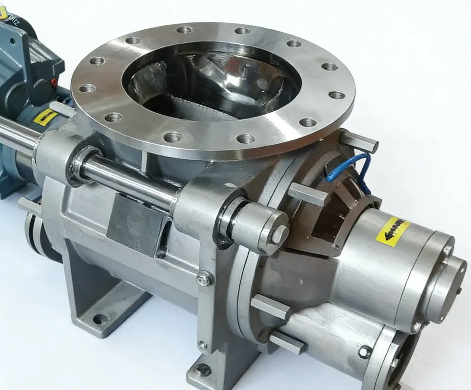
Rotor vane configurations and housing clearances are critical parameters. We manufacture our valves with strict 0.1mm rotor clearances. This precise machining results in a 15 percent reduction in compressed air waste. We also modify flange dimensions to fit non-standard connection points. A pneumatic conveyor system retrofit for non-standard plant configurations relies entirely on this pressure isolation capability.
| Valve Feature | Standard Industry Valve | Doebritz Custom Valve |
| Rotor Vanes | 6-vane configuration | 10-vane staggered |
| Housing Clearance | 0.3mm average | 0.1mm precision |
| Air Leakage Penalty | High (20 percent loss) | Minimal (under 5 percent) |
| Flange Profile | Standard bulky footprint | Low-profile custom fit |
Which Rotor Design Fits Tight Clearances?
A 10-vane staggered rotor design offers the optimal sealing mechanism for tight clearances, ensuring that at least three vanes maintain contact with the housing at all times.
We utilize this specific geometry to lock in pressure across non-standard elevation changes. High-vane-count rotors provide a superior mechanical advantage in high-pressure-drop environments. They compartmentalize the air leakage pathway. This prevents pressurized conveying air from escaping back up into the material feed hopper.
How to Start Your Custom Design?
Success requires a rigorous site audit, precise spatial mapping, and accurate pressure drop recalculations before fabricating any hardware.
You cannot guess your way through an irregular layout. We mandate phased testing to validate theoretical models against actual material flow dynamics. The implementation risks of poor planning include blown seals, plugged lines, and massive production losses. You must map the exact physical constraints and test the bulk density of your specific material. Partnering with a specialized manufacturer like Doebritz ensures these variables are mathematically controlled.
- 3D laser scanning of the facility with accuracy within 2mm
- 5-point pressure differential testing across all proposed elevation changes
- 24-hour continuous load trial to verify thermal expansion limits
- 100 percent validation of material bulk density and particle size distribution
How Can You Transform Your Conveying System Today?
Navigating an irregular facility layout does not mean you have to accept poor material throughput or constant blockages.
By strictly controlling pressure drops, optimizing bend radii, and integrating precision-machined rotary valves, we can transform any chaotic floor plan into a highly efficient conveying route. We have proven that surgical retrofits outperform complete replacements in both cost and downtime.
Do not let building constraints dictate your production capacity. For deep technical support, custom layout analysis, and rotary valve integration tailored to your unique floor plan, contact our engineering team directly at sales@rotaryvalveco.com. We are ready to map your facility and engineer a permanent solution.