


Plant engineers frequently struggle with undersized valves causing severe material bottlenecks or oversized units wasting vital capital. When handling fine powders, guessing the dimensions inevitably leads to erratic feed rates, sudden pipeline blockages, and costly pneumatic line blowby. Many facility operators waste days troubleshooting what they assume is a blower malfunction, only to discover that an improperly dimensioned feeding mechanism is the actual root cause of their system failure.
A precise rotary airlock valve sizing guide for bulk powder handling requires calculating your required volumetric throughput, factoring in material bulk density, and strictly controlling rotor revolutions per minute.
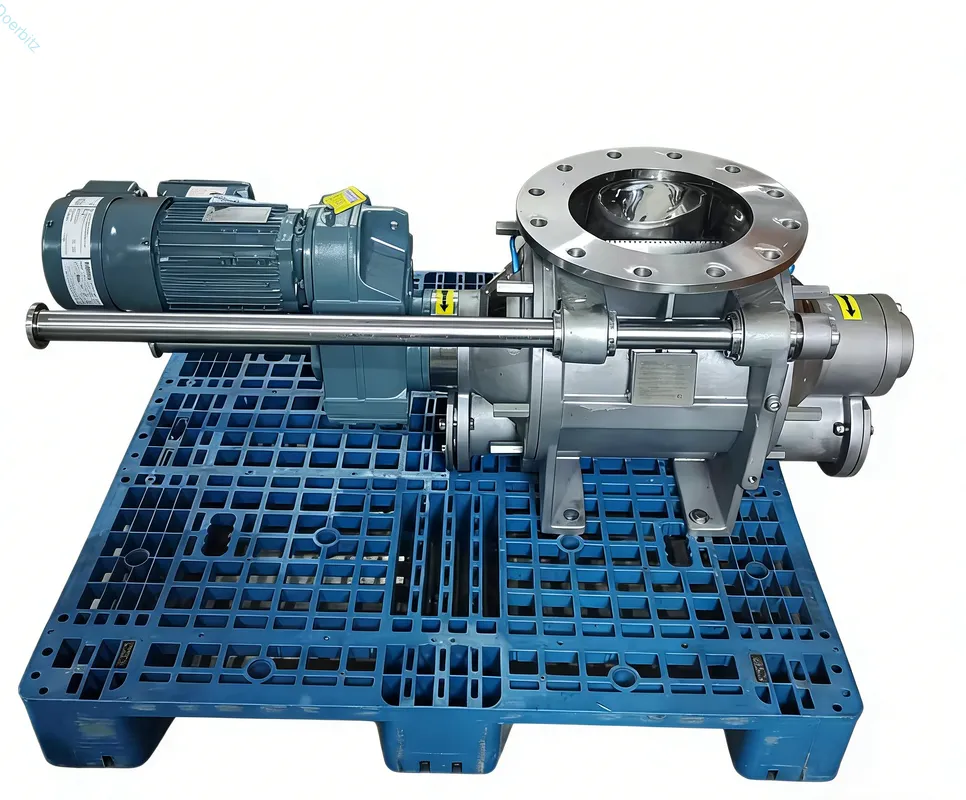
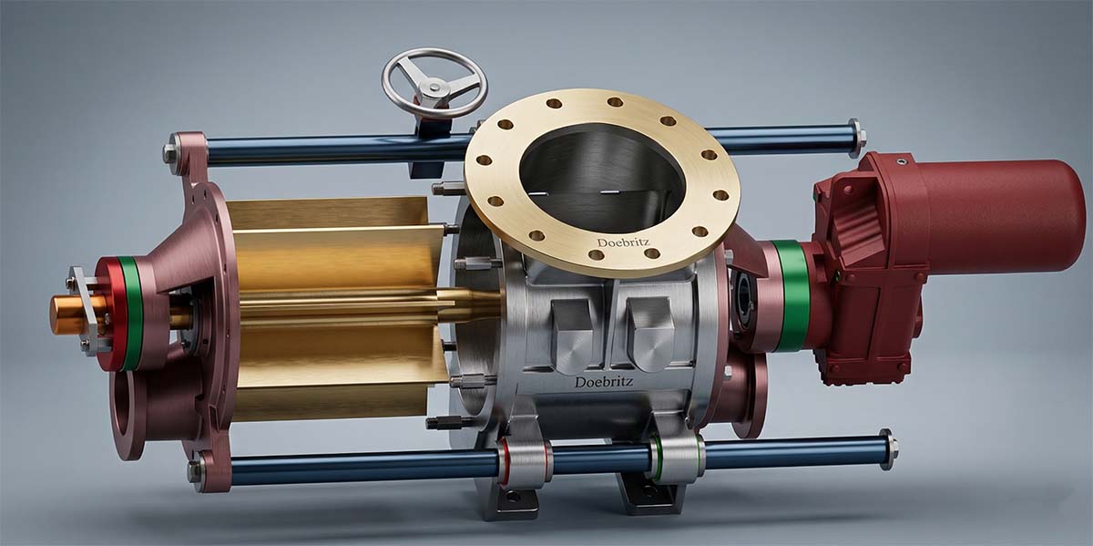
As Doebritz, a professional powder handling rotary valve manufacturer, we created this step-by-step tutorial based on decades of factory floor experience. By following our exact calculation workflow, you will learn how to select the perfect valve dimensions to ensure seamless, leak-free operation. We have engineered thousands of systems globally, and we know exactly where standard sizing charts fail in real-world applications.
Why Does Proper Sizing Matter?
Proper sizing dictates your entire system efficiency; incorrect dimensions lead to severe material bottlenecks, rapid component wear, and inconsistent feed rates.
Engineers often select bulk material handling rotary valves based solely on existing pipe diameters rather than actual process requirements. They look at a 200-millimeter pipe and automatically order a 200-millimeter valve. This mismatch occurs because dynamic material flow characteristics are ignored during the initial drafting phase.
You must size the valve based on volumetric capacity requirements first, then adapt the flange connections to fit your pipeline using transition pieces. Always design your system to allow the rotary valve to operate at a conservative speed, maximizing lifespan while meeting throughput targets.
Running a valve at excessively high speeds to compensate for a small diameter creates catastrophic equipment degradation. For instance, increasing the rotor speed beyond optimal limits can shorten rotor blade lifespan by up to forty percent due to accelerated abrasive wear against the housing bore. Furthermore, an oversized valve operating too slowly will fail to maintain a proper material seal, allowing pressurized conveying air to escape upwards into your storage silo, disrupting the entire material discharge process.
How Do You Calculate Capacity?
You calculate capacity by dividing your target mass flow rate by the material bulk density, then adjusting for the rotor’s specific efficiency.
Selecting the correct dimensions requires a strict mathematical approach rather than relying on generalized capacity tables. Follow this exact sequence to determine your baseline requirements.
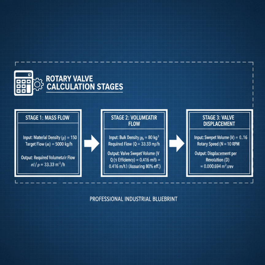
Step 1: Define the target mass flow rate. Identify your required tons per hour, such as 5,000 kilograms per hour. Do not use the maximum theoretical capacity of the plant; use actual operational targets. Oversizing based on theoretical maximums leads to inefficient pocket filling.
Step 2: Determine the aerated bulk density. Measure the loose, aerated bulk density of your specific powder in kilograms per cubic meter. Do not use the packed or tapped density, as powder entering a rotary valve is typically aerated from the upstream process. You can measure this by pouring the powder gently into a container of known volume and weighing it.
Step 3: Calculate the baseline volumetric requirement. Divide your mass flow rate by your aerated bulk density. For example, if your mass flow is 10,000 kilograms per hour and your bulk density is 500 kilograms per cubic meter, your required volumetric flow is 20 cubic meters per hour.
Step 4: Select the valve displacement. Review manufacturer specifications to find a valve model that provides the necessary cubic meters per revolution. You must then divide your total hourly volumetric requirement by sixty minutes, and then by your target operating speed, to find the exact displacement needed per revolution.
What Is Target Fill Efficiency?
Pocket fill efficiency is the actual percentage of the rotor pocket volume occupied by powder during operation, typically between sixty and eighty percent.
Powders never fill a rotor pocket completely due to trapped air resisting the incoming material and the dynamic movement of the spinning rotor. We instruct engineers to use a seventy percent fill factor for standard, free-flowing powders.
However, you must use a fifty percent factor for sluggish, cohesive bulk material handling rotary valves. If you are processing materials like titanium dioxide or carbon black, the powder will cling to the hopper walls and bridge over the inlet, drastically reducing the amount of material that actually enters the pocket. Ignoring this critical efficiency factor means your theoretical calculations will fall entirely short of real-world throughput, leaving your system starved of material.
How Do You Determine Speed?
Rotor speed is determined by matching the required volumetric displacement with the valve capacity per revolution, strictly keeping it under twenty revolutions per minute.
Exceeding twenty-five revolutions per minute prevents powder from fully dropping into the pockets because centrifugal forces and upward air resistance push the material away from the rotor hub. We recommend a strict checklist for speed limits to ensure optimal performance.
Keep the speed under fifteen revolutions per minute for abrasive powders, such as alumina or silica sand, to minimize housing wear and extend maintenance intervals. Keep the speed under twenty revolutions per minute for standard powders like flour or plastic pellets to ensure optimal pocket filling. Slower speeds guarantee that the material has adequate time to drop into the pocket via gravity before the rotor blade seals against the housing.
How To Fix Leakage Problems?
You fix rotary valve leakage problems in pneumatic conveying systems by minimizing rotor tip clearances and installing dedicated body venting solutions.
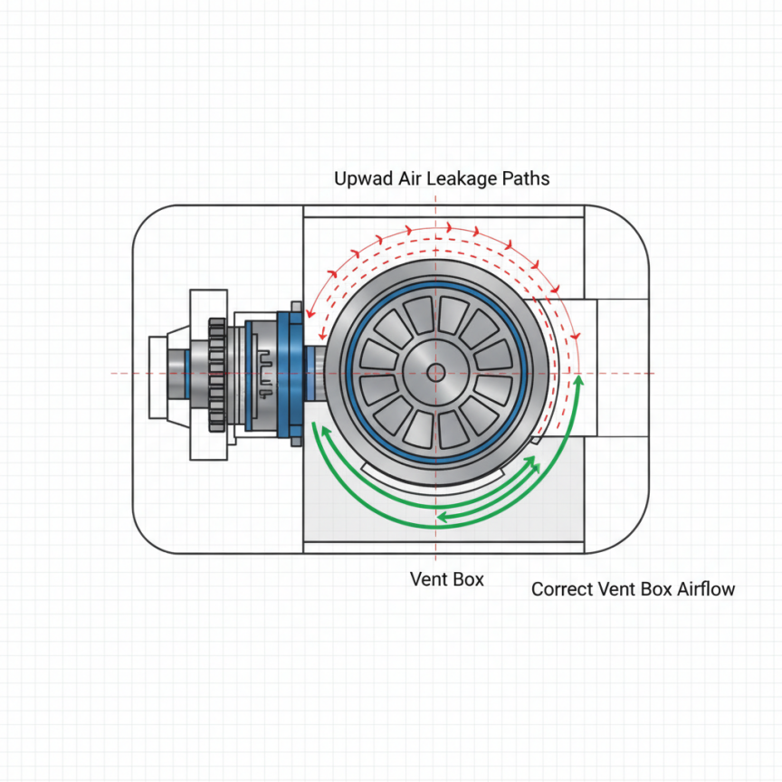
High-pressure air travels upward through the empty returning rotor pockets, blocking incoming powder from entering the valve. This blowby occurs because the pressure below the valve in the conveying line is significantly higher than the atmospheric pressure above it in the feeding hopper. When the empty pocket rotates upwards, it carries a pocketful of compressed air that suddenly expands upon reaching the inlet, creating an invisible wall of air that stops powder dead in its tracks.
Step 1: Check rotor clearances. Lock out the power supply and remove the inspection panel. Measure the rotor-to-housing clearances with a feeler gauge at multiple points. Ensure they are strictly between 0.10 millimeters and 0.15 millimeters for standard temperature applications.
Step 2: Install a venting transition box. Mount a vent baffle directly above the return side of the valve housing. This box gives the expanding air a dedicated pathway to escape before it reaches the primary product flow.
Step 3: Clear the exhaust vent lines. Ensure the exhaust pipe connected to the vent box is at least equal to the vent port diameter and completely free of blockages. Route this line to an independent filter receiver.
Regularly inspect the venting filter bags, as clogged vents immediately recreate rotary valve leakage problems in pneumatic conveying systems. In our engineering experience, a pressure differential of just 0.2 bar across the valve can displace enough air to reduce feed efficiency by thirty percent if clearances exceed 0.20 millimeters and proper venting is neglected.
How Can Doebritz Resolve Challenges?
We resolve complex field challenges by analyzing your exact powder characteristics and engineering custom rotor profiles to eliminate bridging and blowby.
Standard off-the-shelf valves frequently fail when applied to difficult, cohesive, or highly aerated powders in real-world environments. Generic sizing charts do not account for the unique flowability, moisture content, and friction coefficients of specific chemical or food-grade powders. When plant managers rely on generic data, they inevitably face unscheduled downtime and severe maintenance bottlenecks.
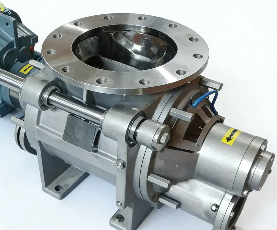
A chemical plant in Germany recently struggled with severe titanium dioxide bridging and massive pressure drops in their pneumatic line. The material was packing tightly into the V-shaped rotor pockets, refusing to discharge into the blowline, which completely stalled their production. Doebritz technical support intervened to diagnose the mechanical failure. We analyzed the highly cohesive nature of their specific powder and the 0.8 bar positive pressure of their conveying pipeline.
We recalculated their system using our proprietary sizing matrix. We replaced their standard unit running at twenty-five revolutions per minute with a larger displacement valve running at only twelve revolutions per minute. This custom unit featured U-shaped rotor pockets, polished internal surfaces to reduce friction, and a customized vent box to handle the displaced air. The bridging stopped immediately, and their pneumatic conveying efficiency increased by thirty-five percent. Partner directly with the manufacturer for technical validation before purchasing based on catalog specifications alone.
How Do You Get Started?
You get started by consulting with our engineering team to validate your calculations and select the exact model for your application.
Proper sizing is not a guessing game; it is a strict engineering process that requires attention to detail. By calculating accurate bulk densities, controlling rotor speeds, and addressing air leakage proactively, your pneumatic systems will run without interruption. As your dedicated manufacturer, Doebritz is ready to review your system parameters and share our operational expertise. If you need expert assistance validating your calculations or selecting the exact model for your application, contact our engineering team today by emailing sales@rotaryvalveco.com to secure your custom sizing assessment.