


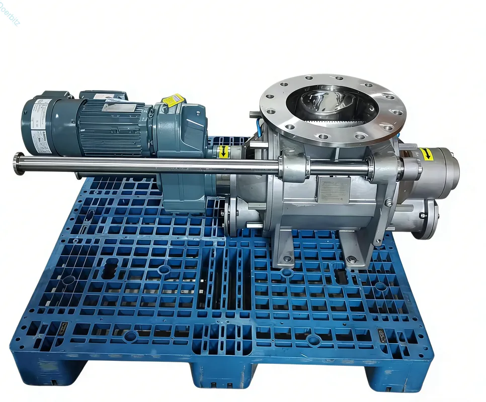
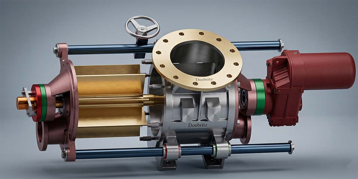
As Doebritz, a professional powder handling rotary valve manufacturer, we frequently see plant engineers and maintenance managers battling severe pressure drops, unexpected conveying line blockages, and product degradation. These operational issues typically stem from pressurized gas escaping backward through the feeding equipment, which severely disrupts the entire bulk material production flow and halts facility output.
Learning how to prevent blow through rotary valve air leakage in pneumatic conveying requires precise rotor-to-housing clearance adjustments, active venting installations, and accurate volumetric capacity calculations. When these mechanical and mathematical elements align, the conveying gas remains in the pipeline where it belongs, ensuring smooth material transfer from the hopper into the pressurized line.
In this step-by-step tutorial, we share our manufacturing expertise to help you diagnose leakage paths, execute proper sizing calculations, and implement proven mechanical solutions to stabilize your system. By following our operational guidelines, you can immediately identify the root causes of pressure loss and apply targeted fixes to keep your powder handling lines running at peak efficiency.
Why Does Air Leakage Occur?
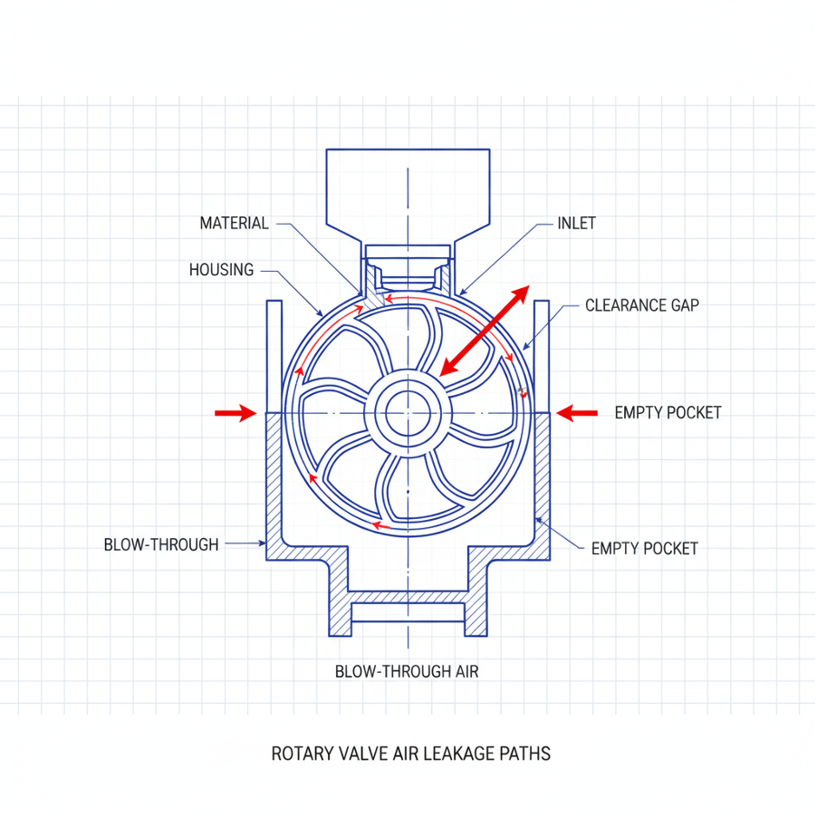
Air leakage occurs because high-pressure conveying gas naturally forces its way upward through rotor clearances and empty returning rotor pockets.
When bulk material drops into the pneumatic conveying line, the high-pressure gas below seeks the path of least resistance, which is often straight up into the upstream feed hopper. This upward blast of air restricts the downward flow of powder, leading to bridging and erratic feed rates.
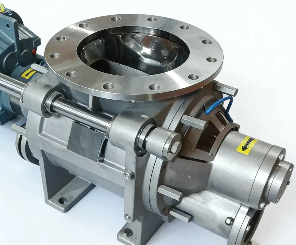
To properly diagnose the issue, we must differentiate between the two distinct mechanical causes of this upward gas flow. Displacement leakage happens when pressurized air fills the empty rotor pockets at the bottom of the housing and travels back up to the top as the rotor turns. Clearance leakage happens when air escapes through the tiny microscopic gaps between the spinning rotor tips and the stationary valve housing.
Minimizing this upward gas migration requires specific machining tolerances and strict operational parameters. If the gaps are too wide, or if the pockets are carrying too much empty volume, the system will inevitably fail to maintain conveying pressure.
As an industry practice, we always recommend establishing a baseline pressure reading before diagnosing clearance wear. You must measure the differential pressure across the valve while the system is running empty, which provides a clear numerical benchmark to compare against future wear.
How Is Valve Sizing Calculated?
Accurate blow through rotary valve sizing calculation for bulk material handling prevents over-pressurization and minimizes the void spaces where air gets trapped.
Oversized valves carry too much empty internal volume, which drastically increases displacement leakage as large empty pockets carry pressurized air back to the hopper. Conversely, undersized valves must run at excessively high RPMs to meet production demands, causing rapid rotor tip wear and exacerbating clearance leakage.
Incorrect capacity estimations lead to poor fill efficiency, forcing the equipment to work harder while losing pneumatic pressure. To solve this, you must calculate the exact dimensions required for your specific material flow using a structured mathematical approach.
Step 1: Determine the exact bulk density of your material in its aerated state. Do not use the packed density, as powder behaves differently when falling into the rotor. Use a one-liter measuring cup and an industrial scale to get a precise kilogram-per-liter reading.
Step 2: Define the required mass flow rate for your production line. For example, note if your system requires moving 5,000 kilograms per hour to feed the downstream packaging silos.
Step 3: Calculate the target volumetric flow rate by dividing the mass flow rate by the bulk density. If your density is 0.5 kilograms per liter, your 5,000-kilogram requirement means you need 10,000 liters of volumetric flow per hour.
Step 4: Apply a fill efficiency factor to your volumetric flow rate. For most industrial powders, we apply a 70% to 80% efficiency rate, meaning the pocket is never entirely full of material. Divide your 10,000 liters by 0.70 to find the true required rotor volume of 14,285 liters per hour.
Never assume 100% pocket fill during your blow through rotary valve sizing calculation for bulk material handling; always calculate based on the specific flowability of the powder. Using a realistic formula ensures you select the exact rotor volume needed to minimize empty air pockets.
What Is The Density Factor?
The density factor is the measured weight of your specific powder per cubic meter under dynamic flowing conditions.
Static bulk density measurements are often misleading because powders aerate and expand when moving through hoppers and valves. To measure dynamic bulk density accurately, you must weigh a one-liter sample of the powder immediately after it has been poured or agitated, without tapping or settling the container. This dynamic measurement directly informs your blow through rotary valve sizing calculation for bulk material handling, ensuring the rotor pockets are sized for the material as it actually behaves during production rather than how it sits in a laboratory beaker.
How To Determine Fill Efficiency?
You determine fill efficiency by assessing the particle size, moisture content, and rotational speed of the rotor.
Free-flowing, dry granular materials running at low speeds can achieve up to 80% fill efficiency. Cohesive, sticky, or highly aerated powders running at high rotational speeds might only achieve 60% fill efficiency. We recommend consulting a material testing chart to assign the correct percentage before finalizing any equipment purchases. If you are handling standard flour or dry cement at 15 RPM, a 70% fill efficiency is a reliable baseline for your mathematical calculations to prevent sizing errors.
How To Stop System Leakage?
We stop system leakage by installing active venting mechanisms, tightening rotor clearances, and upgrading to wear-resistant tip seals.
Existing systems often suffer from blowing air upward, which halts material flow and causes severe bridging in the feed hopper. This mechanical failure usually results from internal wear over time or an inadequate system design that cannot handle the current pneumatic line pressure.
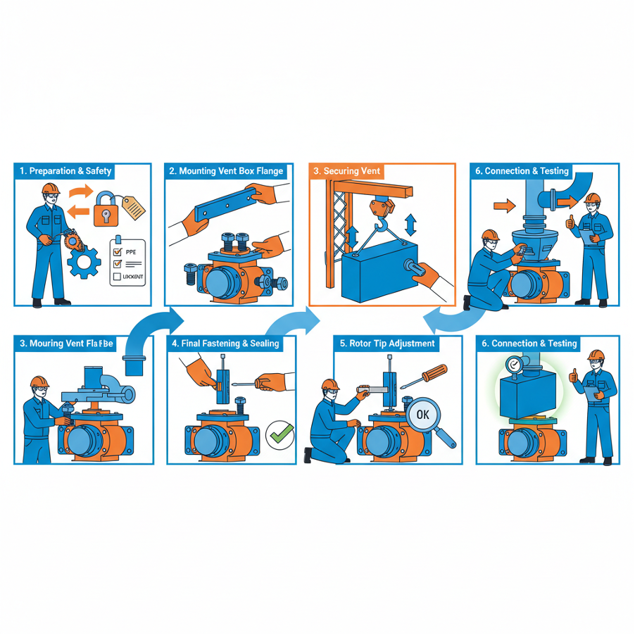
To restore your system, follow this technical operational tutorial to eliminate the leakage paths and stabilize your conveying line.
Step 1: Measure the internal clearances. Lock out the equipment power and tag the control panel. Remove the side inspection plate. Use a standard machinist feeler gauge to measure the gap between the rotor tip and the housing wall at the top, bottom, and both sides. If the gap exceeds 0.20mm for fine powders, immediate mechanical action is required.
Step 2: Install a dedicated vent box. If displacement leakage is high, route the displaced high-pressure air away from the material inlet. Bolt a dedicated venting hopper directly above the returning side of the valve, connecting it to a standalone filter bag or a centralized dust collection system to safely release the trapped air without blowing powder into the room.
Step 3: Upgrade the rotor tips. Remove the standard steel rotor and replace the tips with polyurethane, Teflon, or adjustable hardened steel edges. Using a torque wrench, adjust these new tips outward until the clearance gap is reduced to exactly 0.10mm, completely sealing the clearance leakage path before tightening the locking nuts.
Regularly calibrate the venting filter to ensure it is not clogged with dust, as a blocked vent will force the air right back into the main product flow.
At Doebritz, we recently helped a client in Germany working in the cement industry handling highly abrasive fly ash. They faced severe conveying line blockages at 0.8 bar conveying pressure, bringing their packaging line to a complete halt. Doebritz technical support arrived on-site and diagnosed a massive 0.45mm clearance wear issue caused by the abrasive ash carving into the housing. We guided their maintenance team step-by-step to install our custom tungsten-carbide coated rotor and a specialized body vent. This targeted mechanical intervention successfully reduced air leakage by 85% and restored their full production capacity within 48 hours.
What Are Maintenance Checkpoints?
Critical maintenance checkpoints include measuring radial clearances quarterly, inspecting shaft seals, and monitoring pressure differential gauges.
Even after a perfect installation, leakage slowly returns over time if ignored. Continuous friction from abrasive bulk materials naturally abrades the internal housing and rotor tips, gradually widening the microscopic gaps where air can escape.
To maintain optimal pneumatic conveying efficiency, you must implement a strict mechanical inspection schedule.
Weekly Tasks:
- Check the differential pressure across the valve using the installed analog or digital gauges. A sudden drop indicates a blown seal.
- Inspect the vent box filter for dust buildup and clean it using a compressed air pulse if necessary.
Monthly Tasks:
- Inspect the outboard bearings and shaft seals for any signs of powder ingress, which requires immediate seal purging.
- Listen for unusual scraping noises using an industrial stethoscope, which indicates rotor deflection or bearing failure.
Quarterly Tasks:
- Measure rotor-to-barrel clearances with a feeler gauge on all eight rotor tips to track gradual metal wear.
- Re-adjust adjustable tips if the gap exceeds the 0.20mm threshold, bringing them back to the factory 0.10mm specification.
Keep a digital log of these clearance measurements to predict exactly when a rotor replacement will be necessary, preventing unexpected production downtime.
Preventing air leakage in pneumatic systems requires a combination of precise sizing, dedicated venting, and strict clearance maintenance. As demonstrated by our industry interventions and step-by-step tutorials, addressing these specific mechanical details drastically improves conveying efficiency and prevents material blockages. By calculating the correct volumetric capacity and maintaining tight rotor tolerances, you can keep your production lines moving without interruption.
As a trusted professional manufacturer, Doebritz is ready to help you optimize your bulk material handling systems. If you are experiencing pressure drops, struggling with abrasive material wear, or need precise sizing assistance for your blow through rotary valve, contact our engineering team directly at sales@rotaryvalveco.com for expert technical support and custom solutions.